 |
||||||||||||||||||||||||||||||||||||||||||||||||||||||||||||||||||||||||||||||||||||||||||
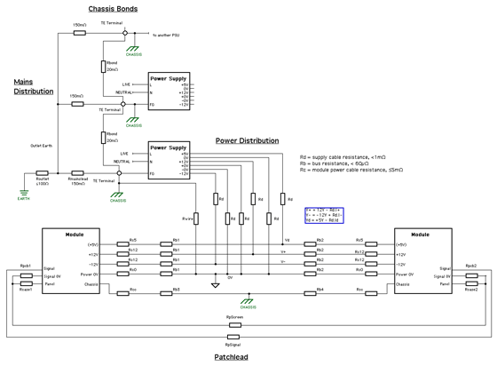
Analysing Power DistributionTextbook theory and conventional wisdom on powering electronic equipment normally considers simple or complex self contained single pieces of equipment such as an item of test gear. It does not extend to cover the case of large distributed modular audio systems like synthesizers or mixing consoles so we have to develop our own theory. When large currents (from, say, 100mA or more) are involved we can no longer consider the wiring carrying it to be an ideal zero resistance. At a current of 1A every milliohm of resistance becomes a millivolt voltage drop and typical systems using pcbs and ribbon cables have voltage drops in hundreds of mV. Furthermore the distribution structure compounds the problems as different varying currents are combined in common wiring. The following diagram shows the significant resistances in power and 0V wiring involved in powering two modules powered by the same PSU patched to each other (we will consider different PSUs later): 
Important points to note are:
In the diagram the resistance of the supply wiring between the PSU and the distribution is shown as Rd. Note that each regulator has a separate supply and return wire so that there are two voltage drops, but they may be considered combined into a resistance of twice Rd with a voltage drop of 2.I.Rd. A system supplying 1A or more will have all that current flowing through the Rds and to limit the voltage drop to <1mV these must be lower than 1mΩ. The voltage drops in the Rds will be seen by all modules in the system as their power supply. This is the major mechanism, known as Common Impedance Coupling, that causes audio bleed and module interaction when modules switching between two or more states taking different currents create waveforms on the distribution rails. The lower the resistance value that Rd can be made the more this effect can be reduced. The resistances of the buses are shown as Rb. Any pcb busboard will have resistance from 10mΩ to 100mΩ contributing more to local coupling. You cannot get enough copper on a pcb to lower its resistance to less than the supply cables and the more that is put on the more difficult it is to solder reliably. By contrast, a 10x15mm busbar across an 84HP width has a resistance of <70µΩ and to make that smaller it is simple to use a larger cross-section bar. This makes the supply cable (Rd) the dominant factor and this may be controlled by adding more cable in parallel. We usually supply two 300mm 6mm² cables giving Rd = 0.5mΩ. The resistances of the power cables to each module are shown as Rc*. The individual power cable resistances, Rc12 and Rc5, would normally be in series with other resistances within the modules and so are not so critical, but the 0V cable resistance, Rc0, is supplying the 0V reference for the whole system and the module will be moved from this potential by the difference between its power currents multiplied by this resistance, (I+ - I-) x Rc. The internal 0V of any two modules are separated by both their Rc0 cable resistances plus the 0V bus between them. With busbars the bar resistance will be negligible compared to the two power cables, but with pcb busboards much more resistance will be added, especially if the modules are on different boards and there is more cable between them. When two modules are patched there is also a cable screen resistance that may be in parallel with the 0V path via the distribution and this may effect voltage drops and the modules' operation. The recommended practise for audio products is now AES48, but most synthesizer designs unfortunately are based on 1970s DIY mistakes. Ideally the cable screen should be connected to a chassis ground unipotential and not conducting signal return currents, but most of the time it is connected to the pcb 0V instead. In the diagram both paths are shown as a resistor, in practise it would be one or the other. If the jacks are wired to the module 0V the pcb trace resistances, Rpcb, are added to the path. With busbar distribution the internal 0V path is much lower that the external patch cable screen and most of the return currents will take that path. With busboard and ribbon cable distribution the internal paths will be higher resistance and similar to the external path so the signal currents will divide in the ratio of the admittances (1/impedance). Copper Wire Resistances
A typical 200mm ribbon cable used in Eurorack will have theoretical resistance of 47mΩ per conductor, but by the time IDC and contact resistances are included the 6 wire 0V resistance will be about 18mΩ from the busboard (which has more resistance). The same length of a KK 0.156" power cable used in 5U systems with two 24/0.2 0V wires will be 12mΩ including the headers each end. Our MFJ10 power connector with four 32/0.2 0V wires with a maximum 500mm length has a resistance of 4.8mΩ to a busbar with about 50µΩ making the 0V resistance between any two modules <10mΩ. Resistances of MetalsTo calculate the resistance of a uniform cross-section solid multiply the resistivity (ρ) by the length in metres and divide by the area in square metres.
* alloy mixtures and impurities will increase these figures. Most metals used for electrical connectors have platings and irregular shapes so the real resistances involved will always be higher than theoretically calculated ones. A 400mm pcb trace 1.5mm wide in 2oz copper, typical of many buscards, will have a resistance of 63.5mΩ @ 20°C. A 400mm aluminium bar 20mm x 10mm will have a resistance of 56µΩ at the same temperature. Voltage drops from the same current in the two will be over 60dB different. |
||||||||||||||||||||||||||||||||||||||||||||||||||||||||||||||||||||||||||||||||||||||||||
