 |
||||||||||||||||||||||||||||||||||||||||||||||||||||||||||||||||||||||||||||||
Module Power Cable SpecificationModular synthesizer systems have always suffered from bad power distribution design with common impedance coupling and 0V reference problems which cause signal bleed and mains hum or buzz. As systems are expanded to larger and larger sizes the wiring and connector resistances become much more significant, particularly with voltage drops in the 0V, making it difficult to conform to modern audio engineering standards and EMC regulations. Poor choices of connectors have a knock on effect that degrade the whole system. We present our new standard that addresses these shortcomings and which will be used in all of our new modules from 2018 onwards and older ones as the pcbs are revised and we recommend that other manufacturers adopt this too. The use of 0.1" pitch data connectors for power and pcb power distribution should be deprecated. A module needs a board to wire connector, but that does not mean that it has to be the same at both ends of the cable and is better if it is not. The features of this standard are:
The Molex Mini-fit Jnr 10-way connector has been chosen as suitable, widely available and unlikely to conflict with other usage. 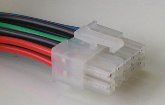
Cable receptacle part # 39-01-2100. 
Cable lengths should be less than 300mm/1ft, but if longer cables or very high currents are needed then 16awg wire and contacts should be used. Cables may be partially populated if the module does not require all lines and an appropriate cable should be supplied with the module. The source of power is a bipolar power supply of the system voltage, usually ±15V or ±12V, but not limited to those voltages. It is intended that a low resistance busbar distribution system is used and that similar coloured wires are joined at that end with a ring terminal. At the module end there are a primary and secondary version of each voltage and its return.
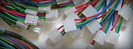
There are four power return wires which would normally be connected to the module 0V plane. The module 0V should not be connected to chassis via any mountings or cable screens. Resistance of the four wires and contacts in parallel should be less than 5 milliohms. Every module in a system is then separated from any other module by less than 10 milliohms, the distribution 0V busbar being less than 1% of this. There are two chassis ground wires in parallel. The pins should be taken to a heavy trace around the perimeter of the pcb or to a heavy gauge wire and connected to jack screens and the module chassis (if present). Jack screens must not be connected to the 0V plane. If there is a dedicated chassis busbar the cable CG wires should be connected to it, otherwise they may be connected to the common 0V busbar. In this way screens are a unipotential and do not share wires carrying DC or signal currents. Signal return currents travel via the 0V distribution and not cable screens. Modules needing other supply voltages (e.g. +5V and +48V) should use a separate similar, but different sized connector so that no conflict arises. Mini-fit Jnr Power CablesUsed by Hinton Instruments and Wiard
32/0.2 or 24/0.2 cable Related Items(Contact us for details.)
|
||||||||||||||||||||||||||||||||||||||||||||||||||||||||||||||||||||||||||||||