 |
|
Professional MIDI GuideAlthough there is no difference in principle between a GM sound module used with a PC in a bedroom and a large studio or stage installation there is a world of difference when it comes to practice. This is a guide to the professional application of MIDI when your livelihood and reputation depend on it. ContentsPart 1:MIDI HardwareThe MIDI 1.0 Specification states:
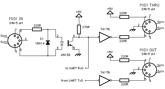
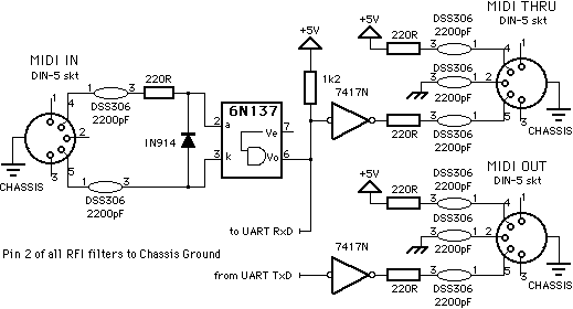
Within a year of its introduction in 1983 MIDI was adopted as standard by the entire electronic musical instrument industry worldwide with a very high degree of compatibility. This level of conformance has never been achieved by lightbulbs, mains plugs or telephones despite official standards organisations to promote them and RS232 is a classic example of the mess that could have resulted. There is no policing of the MIDI standard, it exists as a cooperative commercial standard and anybody deviating from it cuts themselves off from worldwide compatibility. The reason behind the overwhelming success was that the standard was very carefully researched before being revealed publicly. There were no loopholes; hardware, protocol and operation were completely defined. MIDI was economical and apt for its application, yet it immediately had its detractors claiming that it was too slow and heralding MIDI 2.0. Over ten years on it has not been superceded and misconceived attempts to add on to the original concept, like double speed sample dumps and MIDI Timecode, have been less than successful. There are many ways of implementing and applying MIDI depending what market or application is being targeted. The MIDI hardware circuitry was designed to be cheap to implement and foolproof to connect and although it achieved these goals it is also a limitation when used for professional applications. MIDI may be connected incorrectly without damage to itself due to the distribution of its current limiting resistors, but this also limits the maximum cable run to 15 metres which is easily exceeded inbetween two rooms in a studio or on even a medium sized stage. Cheap DIN connectors are hardly the hallmark of professional equipment and are very easily damaged. The pcb mounting sockets may rip up circuit board tracks and cause a write off. Better designed equipment has separate pcbs for the MIDI connectors that may be easily replaced or, better still, durable metal connectors with indirect connection to the circuit boards. We recommend the Deltron range (details in the MIDI Component Sources section) and use them on all our products. Since the beginning of 1996 all equipment sold in Europe must conform to CE EMC requirements and North America already had similar FCC regulations. It is very easy to make a MIDI cable behave like an aerial especially by getting the grounding wrong and since nearly all MIDI equipment contains microprocessors running above 1MHz plenty of radio frequency harmonics may be broadcast. Just one incorrectly wired cable may make an installation illegal! The following circuit shows the additions usually required to ensure the regulations are met (the manufacturer's recommended pcb layout for the filters should be followed carefully).
Note the use of a high speed opto-isolator gate and that there are now two grounds. There is a Chassis Ground that is the outer case of the equipment and is connected to Mains Earth and a 0V ground which is taken out to the MIDI cable screens. It is important that these are kept separate apart from the sole connection through the power supply and that the MIDI screen is not connected to another Earth somewhere else in the setup, e.g. at a patchfield or connector panel. ← Table of Contents | Next: MIDI Cables → |


